7 Tips for Choosing the Best Aluminium Casting Mold

Time:2026-09-29 Author:Henry
0%

Choosing the right Aluminium Casting Mold can determine whether a casting line runs smoothly or produces costly defects. A mold must match the alloy, part geometry, production volume, and required surface finish. Aluminum alloys transfer heat quickly, so thermal control deserves close attention. Poor venting may trap air, while uneven cooling can create cracks, warping, or visible shrinkage.

Practical experience shows that mold selection is rarely based on price alone. A durable steel mold may suit high-volume production, while a simpler mold can work better for short runs or prototypes. Check the mold’s operating temperature, cooling channels, wall thickness, and expected cycle life. Examine sample castings closely. Look for incomplete filling, rough edges, flash, and inconsistent dimensions. Small flaws often reveal larger design problems.

Supplier expertise also matters. Reliable manufacturers should provide material information, dimensional records, maintenance guidance, and realistic service expectations. Ask how the mold was tested before delivery. Confirm whether replacement inserts and repair support are available. These details can reduce downtime when production becomes demanding.

A perfect choice rarely exists. I have seen teams focus on initial cost and overlook cleaning time, which later became expensive. That mistake is easy to repeat. Review the complete process instead of judging one feature. Compare trial results, not promises. The best Aluminium Casting Mold should deliver stable results, manageable maintenance, and consistent quality across repeated cycles. Even then, the decision should be reviewed after real production begins.
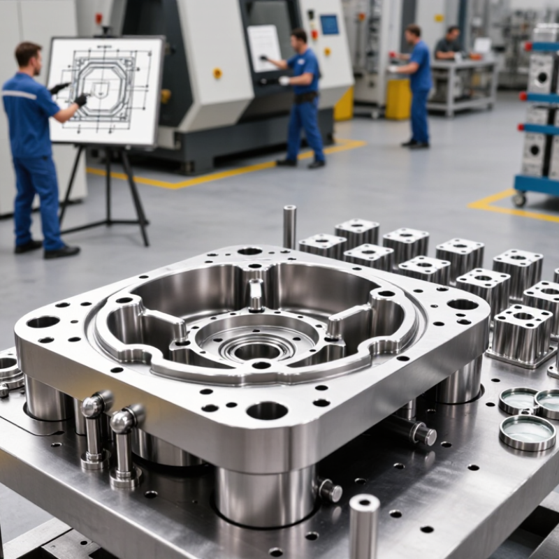
7 Tips for Choosing the Best Aluminium Casting Mold

Classify the Casting Process: Sand, Permanent-Mold, or Die Casting

Choosing an aluminium casting mold starts with classifying the casting process. The wrong category can waste tooling money, time, and metal.

Sand casting suits large, complex parts and small batches. Its expendable sand mold handles undercuts and design changes well. However, surfaces are rougher, and dimensions vary more. Permanent-mold casting uses reusable metal tooling. It delivers cleaner surfaces and better repeatability for medium-volume production. It also needs suitable part geometry and controlled mold temperatures. Die casting fits high-volume, thin-walled components. It offers fast cycles, fine detail, and strong dimensional consistency, but tooling costs are significantly higher.

Scale matters. The International Aluminium Institute reported about 70.6 million tonnes of primary aluminium production in 2023. That figure reflects a massive material system, but it does not justify choosing the fastest process automatically. The U.S. Department of Energy’s Aluminum Industry Technology Roadmap also emphasizes energy efficiency, yield, and process control across aluminium manufacturing. Ask how much scrap each method creates. Then check whether the design can release cleanly from the mold.

Seven practical checks help: batch size, wall thickness, surface finish, dimensional tolerance, alloy, tooling budget, and future revisions. In my experience, engineers often overvalue tolerance and undervalue maintenance access. That is a mistake. Sand may be the wiser choice during early development. Permanent molds often balance cost and consistency. Die casting becomes convincing only when production volume supports its tooling investment. Prototype assumptions can fail. Leave room to learn.

Match Mold Materials to Aluminum’s 660.3°C Melting Point and Thermal Cycling

Aluminum melts at 660.3°C, but a mold must survive more than one hot pour. Repeated heating and cooling cause thermal cycling, surface fatigue, and dimensional movement. Choose mold material for temperature stability, heat transfer, strength, and repairability. Tool steel supports high-pressure casting, while cast iron can work well for slower gravity casting. Graphite offers excellent thermal shock resistance, but it may wear faster in abrasive conditions.

Check the mold’s thermal expansion before cutting steel. A small mismatch can distort the cavity after several cycles. Preheat the mold gradually, especially when its walls vary in thickness. Sudden heating can create hidden cracks. Small cracks matter. Apply a suitable coating to reduce soldering, erosion, and sticking. Keep cooling channels away from sharp corners, where heat concentrates. Use vents and overflow areas to control trapped air and uneven filling.

Measure mold temperature at several points, not only near the gate. Infrared readings can mislead when surfaces are coated or polished. Use contact sensors during process trials. A common mistake is choosing a hard material without considering heat removal. Another is copying an old mold design for a new alloy or wall thickness. Test before scaling. Review cracks, wear marks, and dimensional drift after each trial. The best choice may need adjustment. Thermal calculations help, but real casting evidence should guide the final decision.

Size Runners and Gates for Die-Casting Pressures of 30–150 MPa

Choosing an aluminium casting mold begins with the pressure range, not the mold exterior. Die-casting systems commonly operate around 30–150 MPa, according to NADCA’s Product Specification Standards and ASM Handbook, Volume 15.

Confirm the alloy, casting thickness, and projected area before selecting the mold size. A 100 cm² projected area can create about 1,500 kN of separating force at 150 MPa. Calculate clamp capacity with a safety margin. Do not guess. Design runners to maintain smooth metal flow, while avoiding sudden section changes that trap air. Keep the runner cross-section balanced from the sprue to each cavity. Size gates for the required fill speed, but check gate thickness against planned trimming and solidification. Place vents near the final fill zones, especially around thin ribs and deep pockets. Validate the layout with filling simulation or short-shot trials; simulations can still miss real heat loss.

Gate velocity often falls within approximately 20–60 m/s in high-pressure aluminium casting, depending on alloy and machine settings. The exact value matters. Too slow, and cold shuts may appear. Too fast, and erosion or air entrapment can increase. NADCA guidance stresses process control, while European Aluminium’s casting publications highlight the influence of alloy temperature and solidification behavior. I would leave extra steel around high-wear gate areas. That choice is not elegant, but repairs are expensive. A final review should compare runner volume, overflow capacity, vent locations, and actual machine pressure.

Set Draft, Fillets, and Tolerances According to ISO 8062 Casting Grades

Choosing an aluminium casting mold starts with the casting grade, not appearance alone. ISO 8062 dimensional grades provide a practical tolerance framework for cast dimensions. They do not replace engineering judgment. Confirm the selected grade with your foundry and inspection team before cutting steel.

Set draft according to the withdrawal direction, surface depth, and required finish. A shallow wall may need less draft, while a deep cavity often needs more. Typical aluminium molds may use about 1° to 3° draft, but geometry can change that range. Test the parting line with a physical section or digital mold review. Small errors here can cause scuffing, sticking, or uneven wall thickness.

Add generous fillets at internal corners. Sharp corners can restrict metal flow and concentrate stress during cooling. Keep fillet sizes consistent where possible. Then build the tolerance stack from functional datums, not every nominal dimension. ISO 8062 grades should guide general casting tolerances, while machined interfaces may require tighter control. Measure trial castings at several locations, especially near gates, ribs, and thick sections. Real parts often distort more than the drawing suggests. That is where early assumptions need revisiting. A mold that looks precise on screen may still produce flash, mismatch, or difficult release.

7 Tips for Choosing the Best Aluminium Casting Mold - Set Draft, Fillets, and Tolerances According to ISO 8062 Casting Grades

Tip Design Area Practical Design Guidance ISO 8062 Alignment Design Verification Point
1 Choose the Casting Process First Select the mold concept according to production volume, wall thickness, surface finish, and dimensional requirements. Sand casting generally provides greater flexibility, while gravity permanent-mold and pressure-die casting can provide better repeatability and surface quality. ISO 8062 casting tolerances depend on the casting process and the specified dimensional tolerance grade. Do not assign a single tolerance grade before the process and part geometry are defined. State the process, alloy family, heat-treatment condition, and whether the requirement applies to a casting dimension or a machined feature.
2 Set Draft Angles for Reliable Release Use a practical starting range of 1° to 2° per side for external walls in reusable molds. Consider approximately 2° to 3° per side for deep internal pockets, cores, textured surfaces, or features that may drag during ejection. Minimize draft only after confirming the release direction and mold construction. Draft is a mold-design requirement and is not itself an ISO 8062 dimensional tolerance grade. Additional draft can affect the location of the functional surface and must be included in the dimensional stack-up. Identify the pull direction, parting line, core movement, ejection direction, and the reference face from which the draft is measured.
3 Use Fillets Instead of Sharp Internal Corners Avoid sharp internal corners. A practical starting point is an internal fillet radius of approximately 0.5 to 1.0 times the local wall thickness. For a 4 mm wall, this corresponds to about a 2 to 4 mm internal radius. Use larger transitions where metal flow, thermal gradients, or stress concentration is severe. ISO 8062 controls specified casting dimensions, but it does not replace engineering rules for corner radii. A radius should be dimensioned when it is functionally important; otherwise, define a suitable general-radius rule on the drawing. Check that the fillet does not create an excessive local mass, which can increase shrinkage porosity or extend solidification time.
4 Keep Wall Thickness as Uniform as Possible Use a consistent nominal wall thickness and transition gradually between sections. Avoid abrupt changes such as a heavy boss connected directly to a thin wall. Where additional strength is needed, use ribs, hollow bosses, or blended transitions rather than large solid masses. ISO 8062 tolerance grades do not guarantee soundness. Wall-thickness variation, alloy behavior, feeding, cooling rate, and mold filling must be evaluated separately from dimensional tolerance. Review thin sections for incomplete filling and heavy sections for shrinkage. Confirm that datum locations remain stable after casting and cooling.
5 Select a Realistic ISO 8062 Tolerance Grade Use the tightest grade that the selected process can repeatedly achieve, rather than applying unnecessarily tight tolerances to the entire part. ISO 8062-3 defines dimensional casting tolerance grades from CT1 through CT16; a lower CT number represents a tighter tolerance grade. Typical process capability varies. As a planning guide only, sand castings are often associated with coarser grades such as CT12–CT14, gravity permanent-mold castings commonly use intermediate grades such as CT8–CT10, and pressure-die castings may achieve tighter grades such as CT6–CT9 when geometry and process control permit. Confirm the selected grade with the foundry's capability data. Apply individual tolerances only to functional dimensions and use general tolerances for non-critical features.
6 Separate Casting Dimensions from Machined Dimensions Identify machining datums and provide machining allowance only where material removal is required. Do not combine the as-cast tolerance and the finished-machined tolerance into one unspecified value. ISO 8062 casting tolerances apply to the as-cast condition unless the drawing or specification states otherwise. Machined dimensions must be controlled using the applicable machining tolerances and datum scheme. Mark surfaces as “as cast” or “machined,” define datum targets, and verify that the remaining stock is sufficient after casting variation, distortion, and cleanup.
7 Control Parting Lines, Ejector Marks, and Reference Datums Place the parting line away from sealing faces, bearing seats, and highly visible surfaces whenever possible. Locate ejector marks on non-functional areas and use stable datums for inspection. Add draft and fillets without moving critical functional surfaces outside their tolerance zone. ISO 8062 tolerance selection should be coordinated with the casting's dimensional classification, required machining condition, and inspection method. A tolerance grade alone does not define parting-line mismatch, flash, surface texture, or visual acceptance. Define acceptable flash, mismatch, sink marks, and surface imperfections separately. Inspect critical features from the same datum reference system used for design and machining.

Important: ISO 8062-3 provides casting dimensional and geometrical tolerance classifications, but the achievable grade depends on the casting process, alloy, part size, geometry, mold condition, and production controls. Final values should be confirmed against the applicable ISO 8062 drawing requirements and validated through first-article inspection.

Validate Cooling, Porosity Control, Maintenance, and Expected Tool Life

A reliable aluminium casting mold should be tested under production conditions, not judged by a polished sample. Ask for temperature records across the die after repeated cycles; hot spots near thin ribs can delay solidification and increase scrap. NADCA’s Product Specification Standards for Die Casting (2022) emphasize matching process conditions and die design to the required casting quality. Request documented cooling-channel layouts and trial data, including cycle time and temperature variation. A neat chart helps. But check how it was measured.

Porosity control needs evidence from actual parts. Ask the supplier to report X-ray or CT inspection results by location, alloy, and process setting, rather than quoting one overall defect rate. The American Foundry Society’s metalcasting technical guidance treats shrinkage and gas porosity as distinct defects, so corrective actions should match the cause. Maintenance matters too: review inspection logs for cracked corners, eroded gates, blocked channels, and repair frequency. For expected tool life, request service records from comparable molds, with shots to repair and shots to replacement. Treat estimates as estimates; alloy, cooling, lubrication, and operating discipline all change wear. One uncomfortable question is useful: what failed first on the last similar tool?

FAQS

What pressure range should be considered when sizing an aluminium casting mold?

Many die-casting systems operate around 30–150 MPa. Confirm the actual machine pressure before designing the mold.

How can projected area affect required clamp capacity?

A 100 cm² projected area may create about 1,500 kN of separating force at 150 MPa. Add a safety margin. Do not guess.

How should runners be designed for stable metal flow?

Keep the runner cross-section balanced from the sprue to each cavity. Avoid sudden changes that may trap air.

What should be checked when sizing gates?

Match gate size to the required filling speed. Also check trimming needs, solidification, and possible erosion.

Where should vents and overflows be placed?

Place vents near final fill zones, especially beside thin ribs and deep pockets. These areas often retain air.

What gate velocity is commonly used in high-pressure aluminium casting?

Gate velocity often falls near 20–60 m/s. The correct value depends on the alloy, mold, and machine settings.

Why are draft angles and fillets important in mold design?

Draft supports clean part removal. Fillets improve metal flow and reduce cooling stress at internal corners.

How should casting tolerances be reviewed before cutting steel?

Use the selected casting grade as a guide, not an absolute promise. Check functional datums, machined interfaces, and trial castings.

What can happen when digital mold reviews seem perfect?

Real castings may still show flash, mismatch, distortion, or sticking. Heat loss and release behavior are easy to underestimate.

How can a mold design be validated before production?

Use filling simulation or short-shot trials, then inspect gates, ribs, thick sections, vents, and runner volume. Simulations can still miss reality.

Conclusion

Choosing the right Aluminium Casting Mold begins with identifying the casting process that best fits the part, whether sand casting, permanent-mold casting, or die casting. Each method requires different mold construction, production speed, surface finish, and cost considerations. Mold materials should also withstand aluminum’s 660.3°C melting point, repeated heating and cooling, and the resulting thermal stress without excessive wear or distortion.

For die casting, runners and gates must be sized to handle pressures typically ranging from 30 to 150 MPa, while maintaining balanced filling and reducing turbulence. Draft angles, fillets, and dimensional tolerances should be selected according to the required ISO 8062 casting grades to support easy part removal and consistent quality. Finally, evaluate cooling performance, porosity-control methods, maintenance access, and expected tool life. A well-designed mold should provide stable production, reliable dimensions, efficient heat management, and practical long-term operating costs.


Henry

Henry

Henry is a dedicated marketing professional with a profound expertise in the company's offerings. With years of experience in the industry, he possesses an impressive understanding of the market dynamics and consumer behaviors that drive success. Henry is committed to sharing his insights through......